 AR
AR EN
EN ZH
ZH FR
FR ES
ESنجاح أو فشل تقدير نظام طاقة الاتصالات يعتمد على جودة ملف تحميل الموقع الخاص بك — وليس على الافتراضات العامة لكل محطة قاعدة — لأن ظروف النشر في العالم الحقيقي تحول الحسابات الموحدة إلى أحكام خاطئة مكلفة. يرث معظم مهندسي الاتصالات جداول تقدير الحجم التي تفترض أن كل موقع يستهلك تقريبًا نفس التيار، ولكن في الواقع، يعمل موقع على السطح في حرارة خط الاستواء مع معدات راديو قديمة وموقع على الساحل مع مقومات تصحيح متعرضة للملح في حقائق كهربائية مختلفة تمامًا. الحصول على الأرقام الصحيحة قبل الشراء يعني تجنب النتيجتين اللتين لا يرغب أحد فيهما: محطة طاقة لا يمكنها تحمل الحمل أثناء انقطاع الشبكة، أو نظام كبير جدًا بحيث تستهلك تكاليف رأس المال والوقود هامش التشغيل للمشروع لسنوات.
كيفية بناء ملف تحميل موقع الاتصالات
تقدير حجم نظام طاقة الاتصالات يعتمد فقط على دقة بيانات الحمل التي يبدأ منها. أكثر حالات الفشل شيوعًا التي أراها عبر المشاريع هي استخدام تصنيف لوحة اسم المعدات كقيمة الحمل. تعكس تصنيفات لوحة الاسم الحد الأقصى الممكن استهلاكه تحت ظروف أسوأ — وليس التيار التشغيلي النموذجي. قد يستهلك راديو محطة قاعدة مصنف بـ 1200 واط حوالي 900 واط في حركة المرور العادية ويقفز مؤقتًا إلى 1100 واط خلال ساعات الذروة. تصميم محطة الطاقة حول لوحة الاسم يعني أنك قد قمت بالفعل بتضخيم الحجم بنسبة 25٪ أو أكثر قبل إضافة أي هامش.
يتطلب بناء ملف تحميل حقيقي ثلاث نقاط بيانات لكل قطعة من المعدات النشطة: استهلاك التيار في الحالة الثابتة خلال حركة المرور العادية، الاستهلاك الأقصى خلال ساعات الذروة، وزخم البدء أو الاندفاع عند تشغيل أي معدات تحتوي على محركات أو بنوك مكثفات كبيرة. بالنسبة لموقع محطة قاعدة ماكرو نموذجي، يشمل ذلك وحدات الراديو، معدات النقل الخلفي، أي موجه أو مفتاح للموقع، نظام التحكم البيئي، وأحمال الأمن أو المراقبة. مجموع استهلاك التيار في الحالة الثابتة هو خط الأساس الخاص بك. مجموع الأحمال القصوى — وليس في نفس الوقت، لأن الراديو ومعدات النقل نادرًا ما تصل إلى الذروة في نفس اللحظة — يحدد طلبك الحقيقي الأقصى.
طريقة البدء العملية هي تسجيل تيار الخرج المستمر للمقوم على مدى 72 ساعة تغطي أنماط حركة المرور في أيام الأسبوع وعطلات نهاية الأسبوع. هذا يلتقط التغير اليومي في الحمل ويعطيك متوسطًا وذروة مقاسة بدلاً من الافتراض. إذا لم يتم بناء الموقع بعد، استخدم بيانات مقاسة من أقرب موقع مقارن بنفس تكوين المعدات، نفس المنطقة المناخية، ونمط حركة المرور المماثل. لا تعتمد أبدًا على رقم.
تحديد حجم نواة الطاقة DC
نظام الطاقة DC — عادةً محطة بجهد 48 فولت DC — يتكون من مقومات، وحدة توزيع، ونقطة اتصال البطارية. يتبع تحديد حجم قدرة المقوم مبدأ بسيط بمجرد معرفة ملف الحمل: يجب أن يغطي خرج المقوم أقصى حمل للموقع بالإضافة إلى تيار إعادة شحن البطارية في نفس الوقت، مع وجود احتياطي N+1 على وحدات المقوم.
إذا كان الموقع يستهلك 80 أمبير في الحالة الثابتة ويصل إلى ذروته عند 110 أمبير، وتتطلب مجموعة البطاريات 40 أمبير لإعادة الشحن بعد حدث تفريغ، فإن الطلب الكلي على التيار المستمر أثناء إعادة الشحن هو 150 أمبير. مع احتياطي N+1، إذا كانت كل وحدة مقوم توفر 50 أمبير، فستحتاج إلى أربع وحدات للحمل (150 ÷ 50 = 3) بالإضافة إلى وحدة احتياطية، ليصبح المجموع خمس وحدات، مما يمنح قدرة مصنفة تبلغ 250 أمبير. هذا يضمن أن فشل وحدة واحدة أثناء إعادة الشحن لا يخفض النظام أدنى من متطلبات الحمل. حساب N+1 إلزامي لأي موقع لديه اتفاقية مستوى خدمة تفرض غرامات على التوقف — وفي الاتصالات، تقريبا جميعها تفعل ذلك.
جانب التوزيع يستحق اهتمامًا مساويًا. يجب اختيار تصنيفات قواطع الدوائر وتحديد حجم الكابلات للتيار الأقصى بالإضافة إلى عامل أمان بنسبة 25٪ وفقًا لـ NEC أو ما يعادله محليًا. يسبب توزيع غير مناسب الحجم حرارة، انخفاض الجهد، وتوقفات غير ضرورية سيطاردها الفنيون الميدانيون لعدة أشهر دون تشخيص السبب الجذري. نظام بجهد 48 فولت يعمل عند 100 أمبير عبر كابل بمقاومة إجمالية تصل إلى 0.1 أوم يخفض 10 فولت — وهو أكثر من 20٪ من الجهد الاسمي وسيسبب فشل أو إعادة تشغيل المعدات. توجد جداول تحديد حجم الكابلات لسبب؛ استخدمها، وتحقق من خلال حساب انخفاض الجهد لطول مسار الكابل الخاص بك.
| مكون الحمل | الحالة الثابتة (أ) | الذروة (أ) | ملاحظات |
|---|---|---|---|
| وحدات الراديو (ثلاثة قطاعات) | 55 | 72 | تم قياسها من قبل البائع، نموذجي حضري |
| نقل العودة | 8 | 12 | نقطة نهاية الميكروويف أو الألياف |
| موجه الموقع / المفتاح | 5 | 7 | يشمل أحمال PoE |
| التحكم البيئي | 6 | 22 | شامل بدء الضاغط |
| الأمن / المراقبة | 2 | 2 | تغير ضئيل |
| الإجمالي | 76 | 115 | مجموع القمم الفردية |
سعة احتياطي البطارية التي تعمل
حجم احتياطي البطارية هو المكان الذي تصبح فيه معظم أدلة حجم نظام طاقة الاتصالات حسابية بدون فائدة. الصيغة القياسية — وقت النسخ الاحتياطي بالساعات مضروبًا في تيار الحمل يساوي الأمبير-ساعة المطلوبة — تعمل فقط إذا أخذت أيضًا في الاعتبار شيخوخة البطارية، وانخفاض الأداء بسبب درجة الحرارة، وحدود عمق التفريغ. بطارية VRLA مصنفة بـ 200 Ah عند 25°C وتفريغ لمدة 10 ساعات توفر شيئًا أقرب إلى 140 Ah قابلة للاستخدام عند 35°C بعد عامين من الخدمة. تجاهل عوامل التخفيض هذه وقد يوفر النسخ الاحتياطي لمدة أربع ساعات ساعتين ونصف في الميدان.
لقد أصبح قرار اختيار البطارية أكثر تعقيدًا في السنوات الأخيرة. لا تزال تقنية VRLA هي السائدة في عمليات النشر ذات التكلفة الحساسة، لكن بطاريات فوسفات الحديد الليثيوم (LFP) تكتسب أرضًا في المواقع الجديدة حيث يفضل إجمالي تكلفة الملكية على مدى عشر سنوات الليثيوم. تتحمل بطاريات LFP التفريغ العميق، وتدور أكثر مرات، وتعمل في درجات حرارة أعلى دون تسريع الشيخوخة، وتحتل مساحة أقل — وكلها ذات صلة بحساب الحجم لأنها تغير مقدار السعة التي تحتاج إلى تثبيتها لتوفير مدة النسخ الاحتياطي المعطاة. قد يحتاج الموقع الذي يتطلب 200 Ah من السعة القابلة للاستخدام إلى 400 Ah من VRLA (عند عمق تفريغ 50 بالمئة) أو 250 Ah من LFP (عند 80 بالمئة من عمق التفريغ). يصبح الفرق في الحجم المادي مهمًا في التركيبات على الأسطح أو خزائن الشوارع ذات المساحة المحدودة.
أحد معايير الحجم التي يتم تجاهلها باستمرار هو حد سعة نهاية العمر. تعتبر معظم ضمانات البطارية أن نهاية عمر البطارية عندما تنخفض السعة إلى 80 بالمئة من التصنيف. إذا كان هدف وقت النسخ الاحتياطي الخاص بك هو أربع ساعات عند الحمل الكامل، فقم بحجم السعة الأولية بحيث عند 80 بالمئة من السعة المتبقية — وليس عند 100 بالمئة — لا تزال تلبي متطلبات الأربع ساعات. هذا يعني ضرب السعة التي حسبتها في 1.25 قبل اختيار نموذج البطارية. التكلفة الإضافية صغيرة مقارنة باكتشاف بعد ثلاث سنوات من التشغيل أن وقت النسخ الاحتياطي لم يعد يلبي اتفاقية مستوى الخدمة.
عندما تدخل طاقة الهجين والمولد في المعادلة
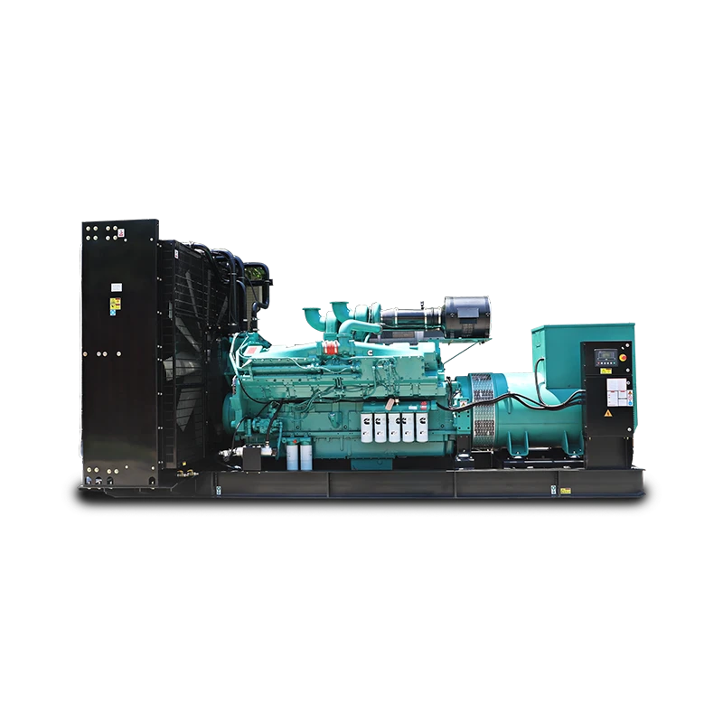
حجم محطة التيار المستمر النقية مع الشبكة والبطارية يغطي العديد من المواقع الحضرية والضواحي بشكل كافٍ. ولكن عندما يكون الموقع خارج الشبكة، غير موثوق به، أو يغذيه خط توزيع ريفي طويل مع انقطاعات متكررة، يصبح تمرين الحجم مشكلة تكامل متعددة المصادر. يحتاج نظام الطاقة الآن إلى تنسيق مدخلات الطاقة الشمسية، وتدوير تخزين البطارية، وتشغيل المولد الديزل — مع حجم المولد ليس فقط للحمل ولكن لإعادة شحن البطارية بدون تشغيل مفرط.
في المشاريع التي قمت بها الدعمانتشرت في جنوب شرق آسيا وأفريقيا، كانت مسألة حجم المولد لمواقع الاتصالات الهجينة تتسبب مرارًا في تعثر الفرق التي كانت ذات خبرة مع محطات التيار المستمر النقية. للمولد في الموقع الهجين وظيفتان: تزويد حمل الموقع خلال فترات انخفاض الشمس الممتدة وإعادة شحن بنك البطاريات عندما يؤدي عمق التفريغ إلى تشغيل المولد. إذا كان بنك البطاريات كبيرًا ومفرغًا بشكل عميق، فإن طلب تيار الشحن يمكن أن يتجاوز طلب الحمل للموقع بشكل كبير. يحتاج الموقع الذي يستهلك 80 أمبير من الحمل مع بنك بطاريات يطلب 60 أمبير من تيار الشحن إلى مولد قادر على توفير 140 أمبير على التيار المستمر — بالإضافة إلى خسائر التحويل من التيار المتردد إلى المستمر عبر المقوم، والتي عادةً تتراوح بين 10 إلى 15 بالمئة. يجب أن يغطي تصنيف القدرة الرئيسي للمولد هذا الحمل المشترك مع عامل تحميل يتراوح بين 70 إلى 80 بالمئة من أجل كفاءة الوقود وطول عمر المحرك.
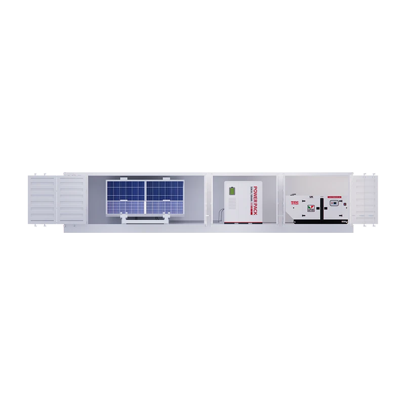
منصة نظام الطاقة الهجينة لشركة Tide Power، التي تتراوح من تكوينات 10 كفا إلى 250 كفا، مصممة حول تحدي التنسيق متعدد المصادر هذا بالذات — دمج مدخلات الطاقة الشمسية، وتخزين بطاريات LFP، وتوليد الديزل مع تبديل بسرعة ميلي ثانية ومنطق التوزيع الآلي. لموقع اتصالات يتطلب 15 كيلواط مستمر مع أربع ساعات من استقلالية البطارية واحتياطي المولد لانقطاعات الشبكة الممتدة، يتدفق حساب الحجم من ملف الحمل إلى الخارج بدلاً من من مواصفات المنتج المسبق التكوين إلى الداخل. يقيس النظام الحمل، وليس العكس. إذا كانت موارد الطاقة الشمسية وملف موثوقية الشبكة لموقعك تشير إلى مزيج مختلف، شارك بيانات الحمل الخاصة بك ويمكننا تأكيد أي تكوين يتطابق — لأن حساب الحجم للمواقع الهجينة في الاتصالات هو بطبيعته خاص بالموقع.
العوامل الميدانية التي تغير الأرقام
الارتفاع، ودرجة الحرارة المحيطة، وسهولة الوصول إلى الموقع لا تظهر في معظم جداول حساب الحجم، ولكنها في الممارسة العملية تتجاوز عددًا مفاجئًا من القيم المحسوبة. مولد ديزل مصنف بـ 100 كيلواط عند مستوى سطح البحر و25°C يوفر حوالي 90 كيلواط عند ارتفاع 1500 متر و35°C — وبعض مواقع الاتصالات في مصر تقع أعلى من ذلك. كما أن كفاءة المقوم تتدهور عند درجات حرارة مرتفعة، عادةً بفقدان 1 إلى 2 بالمئة من الإنتاج المصنف لكل 5°C فوق 40°C من درجة الحرارة المحيطة. إذا رأى موقع في منطقة صحراوية درجات حرارة داخل الخزانة تتجاوز 50°C خلال بعد ظهر الصيف، فإن تصنيف لوحة الاسم للمقوم يحتاج إلى تخفيض بنسبة 5 إلى 10 بالمئة.
تغيير وصول الموقع لتوصيل الوقود يحول حساب استقلالية المولد. الموقع الذي يتلقى وقودًا مرة واحدة في الشهر خلال الموسم الجاف، ولكنه قد يُقطع لمدة ستة أسابيع خلال موسم الأمطار، يحتاج إلى خزان وقود بحجم يتناسب مع أسوأ فترة، وليس المتوسط. قد يغطي خزان البطن القياسي بسعة 1000 لتر مجموعة من التشغيل لمدة أسبوعين عند حمولة جزئية؛ مضاعفة حجم الخزان أو إضافة خزان خارجي محاط يضيف تكلفة ولكنه يلغي خطر توقف الموقع عن العمل لأن شاحنة الوقود لا يمكنها المرور. هذه ليست مشكلة في حجم المولد من الناحية الكهربائية، لكنها بالتأكيد مشكلة في حجم النظام من الناحية التشغيلية — وتستحق أن تكون جزءًا من دليل الحجم لأنها تحدد ما إذا كان الموقع سيظل متصلًا على الإنترنت.
متطلبات الحماية البيئية تتزايد أيضًا مع ظروف الموقع، وليس فقط مع مواصفات المعدات. المواقع الساحلية التي تتعرض لرذاذ الملح تحتاج إلى حاويات ذات تصنيف IP أعلى ومعدات مقاومة للتآكل. المواقع المعرضة لحرائق الغابات قد تحتاج إلى عادم مزود بمانع شرر ومساحات إضافية للتباعد. هذه العوامل لا تغير حساب الكيلوواط، لكنها تغير اختيار المعدات المادية وبالتالي مواصفات الشراء. دليل الحجم الذي يتجاهلها ينتج تصميمًا كهربائيًا صحيحًا تقنيًا مرتبطًا بمعدات تفشل مبكرًا في بيئتها التشغيلية الفعلية.
من حساب الحجم إلى الشراء
تمت عملية قياس الحجم بشكل كامل وتنتج مجموعة من القيم: الحمل الكلي على التيار المستمر، سعة المقوم مع الاحتياطي، سعة البطارية مع التخفيض، تصنيف المولد إذا كان ذلك مناسبًا، وأي عوامل تخفيض بيئية. هذه القيم تترجم مباشرة إلى مواصفات الشراء — ولكن فقط إذا تم توثيقها مع فرضيات الاشتقاق الخاصة بها. المواصفة التي تقول “مزرعة تيار مستمر 48 فولت، مقوم 250 أمبير، بطارية 400 أمبير ساعة” دون شرح ملف الحمل، فرضيات درجة الحرارة، والهدف من الاستقلالية وراء تلك الأرقام تدعو المورد لتقديم عرض بأرخص المعدات التي تلبي الأرقام فقط بدلاً من المعدات المناسبة لظروف الموقع الفعلية.
خطوة الشراء هي أيضًا المكان الذي تلتقي فيه تعقيدات تكامل المصادر المتعددة بالواقع التجاري. ليس كل مورد لديه خبرة ميدانية مع مواقع الاتصالات الهجينة التي تجمع بين الطاقة الشمسية، والتخزين، وأصول المولد تحت بنية تحكم واحدة. قد تكون قائمة المعدات بسيطة، لكن تكامل النظام — التأكد من أن وحدة تحكم شحن الشمس، ونظام إدارة البطارية، ووحدة تحكم المقوم، ووحدة تحكم التشغيل التلقائي للمولد تتفاعل بشكل صحيح — هو المكان الذي تتعثر فيه المشاريع. المورد الذي يمكنه توفير جميع المكونات الثلاثة من فريق هندسي واحد يلغي مخاطر التكامل التي يسببها التوريد المجزأ.
إذا كنت تعمل حاليًا على قياس نظام طاقة اتصالات والنطاق يشير إلى تكوين هجين أو متعدد المصادر، فمن الجدير تأكيد نطاق التكامل قبل الانتهاء من قائمة المعدات. تواصل عبر [email protected] أو اتصل على +86 591 2806 8999 مع ملف الحمل وظروف الموقع — الحجم الصحيح يهم أكثر من الحجم السريع.
الأسئلة الشائعة حول قياس نظام طاقة الاتصالات
ما هو الخطأ الأكثر شيوعًا في قياس أحجام محطات التيار المستمر للاتصالات؟
تجاهل تيار إعادة شحن البطارية عند قياس سعة المقوم. معظم المهندسين يجمعون بشكل صحيح حمولة المعدات ويضيفون وحدة N+1، لكن ينسون أنه بعد انقطاع التيار الكهربائي يجب على المقوم أن يغذي الموقع ويعيد شحن بنك البطاريات المستهلكة في الوقت نفسه. موقع يستهلك عادة 80 أمبير يمكن أن يطلب بسهولة 130 أمبير أو أكثر خلال الساعة الأولى من إعادة الشحن. وحدات المقوم المصنفة لتحميل المعدات فقط ستعمل بكامل طاقتها — وبدون احتياطي — خلال أسوأ فترة استرداد. لقد رأيت مواقع حيث أدى هذا الإغفال إلى أن حدث انقطاع التيار الكهربائي للمرة الثانية أثناء إعادة شحن البطارية، مما أدى إلى توقف الموقع تمامًا، لأن المقوم لم يستطع تحمل الحمل المشترك.
كيف يغير 5G قياس نظام طاقة الاتصالات؟
يضيف 5G متغيرين جديدين: كثافة طاقة أعلى لكل موقع وعدد أكبر من المواقع. يمكن لموقع 5G macro مع هوائيات MIMO الضخمة والربط الخلفي المطور أن يستهلك طاقة أكثر بنسبة تتراوح بين 50 إلى 100 بالمائة مقارنة بموقع 4G مماثل، مما يدفع محطات التيار المستمر الحالية إلى ما وراء هوامش تصميمها الأصلية. بالإضافة إلى زيادة كل موقع، فإن تكثيف شبكات 5G يعني المزيد من الخلايا الصغيرة والمواقع على مستوى الشارع، والعديد منها يفتقر إلى المساحة المادية لمحطات التيار المستمر التقليدية. تفضل هذه المواقع حلول البطاريات الليثيوم المدمجة، وعند محدودية الوصول إلى الشبكة، أنظمة هجينة صغيرة. لا يتغير منهج قياس الحجم بشكل جوهري — لا زال تحديد ملف الحمل يأتي أولاً — لكن أرقام الحمل تتصاعد بسرعة أكبر مما توقعه العديد من مخططي الشبكات.
هل يمكن للطاقة الشمسية فقط تشغيل محطة قاعدة اتصالات؟
في معظم المناخات، لا — ليس بدون تخزين بطاريات كبير أو دعم من المولد. محطة قاعدة تستهلك حوالي 1.5 كيلووات بشكل مستمر تحتاج تقريبًا إلى 36 كيلوواط ساعة يوميًا. مجموعة شمسية تنتج أقصى طاقة لمدة خمس ساعات شمسية مكافئة يوميًا ستحتاج إلى حوالي 7.2 كيلووات من الألواح فقط لتلبية الاستهلاك اليومي، بالإضافة إلى سعة البطارية للعمل ليلاً وفي الأيام الغائمة. للمواقع في المناطق المشمسة باستمرار، يمكن للطاقة الشمسية أن تحمل غالبية الحمل، لكن يظل المولد أو الاتصال بالشبكة ضروريًا لفترات انخفاض الإشعاع الممتدة. سؤال الحجم ليس هل يمكن للطاقة الشمسية تشغيل الموقع — بل كم تقلل من وقت تشغيل المولد واستهلاك الوقود على مدى عمر النظام. في المشاريع التي دعمتها، عادةً ما يقلل نظام هجينة من الطاقة الشمسية والبطارية والمولد من وقت تشغيل المولد بنسبة تتراوح بين 60 إلى 80 بالمائة مقارنة بالتشغيل فقط على المولد، مما يغير لوجستيات الوقود وجدول صيانة المولد بشكل كبير.
هل يجب أن أقيّم الحجم على الحمل الحالي أم التوسع المستقبلي؟
قم بقياس البنية التحتية الأساسية — رف المقوم، حافلة التوزيع، مسارات الكابلات — وفقًا لتوقعات توسع واقعية لمدة خمس سنوات، ولكن قم بملء وحدات المقوم وسعة البطارية للحمل الحالي بالإضافة إلى سنة واحدة. تكلف رفوف المقوم ذات الفتحات الفارغة أكثر قليلاً من الأرفف الصغيرة المملوءة بالكامل، لكنها تتيح توسيع السعة دون استبدال المصنع بأكمله. تعتبر بنوك البطاريات أقل مرونة؛ إضافة السعة لاحقًا تعني خلط البطاريات القديمة والجديدة، مما يخلق سلوك شحن وتفريغ غير متساوٍ. إذا كان التوسع خلال ثلاث سنوات مؤكدًا، فقم بقياس بنك البطاريات للحمل المتوقع الآن ووافق على العقوبة الطفيفة لكفاءة تشغيل بنك أكبر عند حمل جزئي. إذا كان التوسع غير مؤكد، فقم بقياس الحمل الحالي وخطط لاستبدال بنك البطاريات عند حدوث التوسع. شارك جدول التوسع وتوقعات الحمل عبر [email protected] — يمكننا المساعدة في تأكيد أي النهجين أقل تكلفة على مدى عمر خدمة النظام.
إذا كنت مهتمًا، اطلع على هذه المقالات ذات الصلة:
تيد باور وMWM يعمقان الشراكة في اجتماع استراتيجي حول مولدات الغاز وحلول الطاقة
القوة الكامنة: الكشف عن المولدات الصناعية المتقدمة من Tide Power
كيفية تحديد متطلبات الواط
الدعوة إلى تعزيز شبكات الكهرباء بشكل أقوى لتلبية الطلبات المتزايدة على الذكاء الاصطناعي
تم الاعتراف بتايد باور كشركة تكنولوجيا عالية وطنية