 EN
EN ZH
ZH FR
FR ES
ES AR
ARTelecom power system sizing succeeds or fails on the quality of your site load profile — not on generic per-BTS assumptions — because real-world deployment conditions turn standardized calculations into costly misjudgments. Most telecom engineers inherit sizing spreadsheets that assume every site draws roughly the same current, but in practice a rooftop site in equatorial heat with aging radio equipment and a coastal site with salt-exposed rectifiers operate in completely different electrical realities. Getting the numbers right before procurement means avoiding the two outcomes nobody wants: a power plant that cannot hold the load during grid outage, or a system so oversized that capital and fuel costs eat into the project’s operating margin for years.
How to Build a Telecom Site Load Profile
A telecom power system sizing exercise is only as accurate as the load data it starts from. The most common failure mode I see across projects is using the equipment nameplate rating as the load value. Nameplate ratings reflect maximum possible draw under worst-case conditions — not typical operating current. A base station radio rated at 1,200 W may draw 900 W in normal traffic and spike briefly to 1,100 W during peak hours. Design the power plant around the nameplate and you have already oversized by 25 percent or more before adding any margin.
Building a real load profile requires three data points per piece of active equipment: steady-state current draw at normal traffic, peak draw during busy-hour loading, and inrush or startup surge for any equipment with motors or large capacitor banks. For a typical macro BTS site this includes the radio units, backhaul transmission equipment, any site router or switch, the environmental control system, and security or monitoring loads. The sum of steady-state draws is your baseline. The sum of peak draws — not simultaneously, because radios and transmission equipment rarely peak at the same moment — determines your true maximum demand.
A practical starting method is to log DC output current at the rectifier over a 72-hour period covering both weekday and weekend traffic patterns. This captures diurnal load variation and gives you a measured average and peak rather than an assumed one. If a site is not yet built, use measured data from the nearest comparable site with similar equipment configuration, same climate zone, and similar traffic profile. Never rely on a vendor-supplied “typical site” number without validating it against your own network data.
Sizing the DC Power Core
The DC power system — typically a 48V DC plant — consists of rectifiers, a distribution unit, and the battery connection point. Sizing the rectifier capacity follows a straightforward principle once the load profile is known: rectifier output must cover the maximum site load plus the battery recharge current simultaneously, with N+1 redundancy on the rectifier modules.
If a site draws 80 A steady-state and peaks at 110 A, and the battery bank requires 40 A for recharge after a discharge event, the total DC demand during recharge is 150 A. With N+1 redundancy, if each rectifier module delivers 50 A, you need four modules for the load (150 ÷ 50 = 3) plus one redundant, so five modules total, giving a rated capacity of 250 A. This ensures a single module failure during recharge does not drop the system below load requirements. The N+1 calculation is mandatory for any site with a service-level agreement that penalizes downtime — and in telecom, nearly all of them do.
The distribution side deserves equal attention. Circuit breaker ratings and cable sizing must be selected for peak current plus a 25 percent safety factor per NEC or local equivalent. Undersized distribution creates heat, voltage drop, and nuisance tripping that field technicians will chase for months without diagnosing the root cause. A 48V system running at 100 A through a cable with even 0.1 Ω of total loop resistance drops 10 V — that is more than 20 percent of the nominal voltage and will cause equipment to fault or reboot. Cable sizing tables exist for a reason; use them, and verify with a voltage drop calculation for your specific cable run length.
| Load Component | Steady-State (A) | Peak (A) | Notes |
|---|---|---|---|
| Radio Units (3-sector) | 55 | 72 | Vendor-measured, urban macro |
| Backhaul Transmission | 8 | 12 | Microwave or fiber terminal |
| Site Router/Switch | 5 | 7 | Includes PoE loads |
| Environmental Control | 6 | 22 | Compressor inrush included |
| Security/Monitoring | 2 | 2 | Negligible variation |
| Total | 76 | 115 | Sum of individual peaks |
Battery Backup Capacity That Works
Battery backup sizing is where most telecom power system sizing guides get formulaic without being useful. The standard formula — backup time in hours multiplied by load current equals required ampere-hours — works only if you also account for battery aging, temperature derating, and depth-of-discharge limits. A VRLA battery rated at 200 Ah at 25°C and a 10-hour discharge rate delivers something closer to 140 usable Ah at 35°C after two years of service. Ignore these derating factors and your four-hour backup might deliver two and a half hours in the field.
The battery selection decision tree has grown more complex in recent years. VRLA remains the dominant technology for cost-sensitive deployments, but lithium iron phosphate (LFP) banks are gaining ground in new-build sites where total cost of ownership over ten years favors lithium. LFP batteries tolerate deeper discharge, cycle more times, operate at higher temperatures without accelerated aging, and take up less floor space — all relevant to a sizing calculation because they change how much capacity you actually need to install to deliver a given backup duration. A site requiring 200 Ah of usable capacity might need 400 Ah of VRLA (at 50 percent depth of discharge) or 250 Ah of LFP (at 80 percent DoD). The physical footprint difference becomes material in space-constrained rooftop or streetside cabinet installations.
One sizing parameter that gets overlooked consistently is the end-of-life capacity threshold. Most battery warranties consider the battery end-of-life when capacity falls to 80 percent of rated. If your backup time target is four hours at full load, size the initial capacity so that at 80 percent remaining capacity — not at 100 percent — you still meet the four-hour requirement. This means multiplying your calculated capacity by 1.25 before selecting the battery model. The incremental cost is small compared to discovering three years into operations that your backup time no longer meets the SLA.
When Hybrid and Generator Power Enter the Equation
Pure DC plant sizing with grid and battery covers many urban and suburban sites adequately. But when the site is off-grid, grid-unreliable, or fed by a long rural distribution line with frequent outages, the sizing exercise becomes a multi-source integration problem. The power system now needs to coordinate solar PV input, battery storage cycling, and diesel generator starts — with the generator sized not just for load but for battery recharge without excessive runtime.
In projects I have supported across Southeast Asia and Africa, the generator sizing question for hybrid telecom sites repeatedly tripped up teams that were experienced with pure DC plants. A generator at a hybrid site has two jobs: supply the site load during extended low-solar periods and recharge the battery bank when depth of discharge triggers a generator start. If the battery bank is large and deeply discharged, the recharge current demand can exceed the site load demand by a significant margin. A site drawing 80 A of equipment load with a battery bank calling for 60 A of recharge current needs a generator capable of delivering 140 A at the DC bus — plus AC-to-DC conversion losses through the rectifier, typically 10 to 15 percent. The generator’s prime power rating must cover this combined load with a 70 to 80 percent loading factor for fuel efficiency and engine longevity.
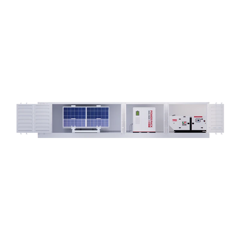
Tide Power’s hybrid power system platform, spanning 10 kVA to 250 kVA configurations, is designed around this exact multi-source coordination challenge — integrating solar input, LFP battery storage, and diesel generation with millisecond-level switching and automated dispatch logic. For a telecom site requiring 15 kW continuous with four hours of battery autonomy and generator backup for extended grid outages, the sizing calculation flows from the load profile outward rather than from a pre-configured product spec inward. The system scales to the load, not the other way around. If your site’s solar resource and grid reliability profile suggest a different mix, share your load data and we can confirm which configuration matches — because the sizing exercise for hybrid telecom is site-specific by nature.
Field Factors That Change the Numbers
Altitude, ambient temperature, and site accessibility do not appear in most sizing spreadsheets, but in practice they override a surprising number of calculated values. A diesel generator rated at 100 kW at sea level and 25°C delivers roughly 90 kW at 1,500 meters and 35°C — and some telecom sites in Latin America and Central Asia sit higher than that. Rectifier efficiency also degrades at elevated temperatures, typically losing 1 to 2 percent of rated output per 5°C above 40°C ambient. If a site in a desert region sees cabinet interior temperatures above 50°C during summer afternoons, the rectifier nameplate rating needs derating by 5 to 10 percent.
Site access for fuel delivery changes the generator autonomy calculation. A site that gets fuel deliveries once a month during dry season but may be cut off for six weeks during rainy season needs a fuel tank sized for the worst-case interval, not the average. The standard 1,000-liter belly tank under a generator set might cover two weeks of runtime at partial load; doubling the tank or adding an external bunded tank adds cost but eliminates the risk of a site going dark because a fuel truck could not get through. This is not a generator sizing issue in the electrical sense, but it is absolutely a system sizing issue in the operational sense — and it belongs in the sizing guide because it determines whether the site stays online.
Environmental protection requirements also scale with site conditions, not just equipment specs. Coastal sites with salt spray need higher IP-rated enclosures and corrosion-resistant hardware. Sites in wildfire-prone areas may need spark-arrested exhaust and additional clearance zones. These factors do not change the kilowatt calculation, but they change the physical equipment selection and therefore the procurement specification. A sizing guide that ignores them produces a technically correct electrical design attached to equipment that fails prematurely in its actual operating environment.
From Sizing Calculation to Procurement
A completed sizing exercise produces a set of values: total DC load, rectifier capacity with redundancy, battery capacity with derating, generator rating if applicable, and any environmental derating factors. These values translate directly into a procurement specification — but only if they are documented with their derivation assumptions. A spec that says “48V DC plant, 250 A rectifier, 400 Ah battery” without explaining the load profile, temperature assumptions, and autonomy target behind those numbers invites a supplier to quote the cheapest equipment that meets the bare numbers rather than equipment appropriate for the actual site conditions.
The procurement step is also where multi-source integration complexity meets commercial reality. Not every supplier has field experience with hybrid telecom sites that combine solar, storage, and generator assets under one control architecture. The equipment list might be straightforward, but the system integration — making sure the solar charge controller, battery management system, rectifier controller, and generator auto-start controller all interoperate correctly — is where projects stall. A supplier that can provide all three components from a single engineering team eliminates the integration risk that fragmented sourcing introduces.
If you are working through a telecom power system sizing exercise right now and the numbers point toward a hybrid or multi-source configuration, it is worth confirming the integration scope before finalizing the equipment list. Reach out at [email protected] or call +86 591 2806 8999 with your load profile and site conditions — sizing right matters more than sizing fast.
Common Questions About Telecom Power System Sizing
What is the most common sizing mistake in telecom DC plants?
Ignoring battery recharge current when sizing rectifier capacity. Most engineers correctly sum the equipment load and add an N+1 module, but forget that after a grid outage the rectifier must simultaneously power the site and recharge a depleted battery bank. A site that normally draws 80 A can easily demand 130 A or more during the first hour of recharge. Rectifier modules rated for the equipment load alone will be running at full capacity — and with no redundancy — during the worst-case recovery period. I have seen sites where this oversight meant that a second grid event during battery recharge dropped the site entirely, because the rectifier could not hold the combined load.
How does 5G change telecom power system sizing?
5G adds two new variables: higher per-site power density and more sites. A 5G macro site with massive MIMO antennas and upgraded backhaul can draw 50 to 100 percent more power than a comparable 4G site, which pushes existing DC plants beyond their original design margins. Beyond the per-site increase, the densification of 5G networks means more small cells and street-level sites, many of which lack the physical space for traditional DC plants. These sites favor compact lithium battery solutions and, where grid access is limited, small hybrid systems. The sizing methodology does not change fundamentally — load profiling still comes first — but the load numbers are climbing faster than many network planners anticipated.
Can solar power alone run a telecom base station?
In most climates, no — not without either substantial battery storage or generator backup. A base station drawing 1.5 kW continuously needs roughly 36 kWh per day. A solar array producing peak power for five equivalent sun hours per day would need about 7.2 kW of panels just to meet daily consumption, plus battery capacity for overnight and cloudy-day operation. For sites in consistently sunny regions, solar can carry the majority of the load, but a generator or grid connection remains necessary for extended low-irradiance periods. The sizing question is not whether solar can run the site — it is how much solar reduces generator runtime and fuel consumption over the system’s life. In projects I have supported, a well-sized solar-battery-generator hybrid typically cuts generator runtime by 60 to 80 percent compared to generator-only operation, which changes the fuel logistics and generator maintenance schedule significantly.
Should I size for current load or future expansion?
Size the core infrastructure — rectifier shelf, distribution bus, cable pathways — for a realistic five-year expansion forecast, but populate rectifier modules and battery capacity for current load plus one year. Rectifier shelves with empty module slots cost marginally more than fully populated smaller shelves but allow capacity expansion without replacing the entire plant. Battery banks are less flexible; adding capacity later means mixing old and new batteries, which creates uneven charge and discharge behavior. If expansion within three years is certain, size the battery bank for the forecast load now and accept the minor efficiency penalty of running a larger bank at partial load. If expansion is uncertain, size for current load and plan to replace the battery bank when expansion occurs. Share your expansion timeline and load forecast at [email protected] — we can help confirm which approach costs less over the system’s service life.
If you’re interested, check out these related articles:
Tide Power & MWM Deepen Partnership in Strategic Meeting on Gas Generator and Power Solutions
The Power Within: Unveiling the Advanced Industrial Generators from Tide Power
How to Determining Wattage Requirements
Advocating for Stronger Electricity Grids to Meet Rising AI Demands
Tide Power has been recognized as a national high-tech enterprise