 EN
 ZH
 FR
 ES
 AR
Smart microgrid reliability is decided in the worst hour a site will ever face, not in the average hour the design was sized for: a loaded feeder, a low sun, a utility supply that has just dropped, and a battery already partly drained by the morning peak. Most of the failures that matter trace back to three assumptions that were never checked against each other. How much firm capacity really exists, what happens during the transition between operating modes, and whether the protection still trips once the fault current falls. The equipment list rarely explains an outage. The way the sources interact does.
What smart microgrid reliability actually depends on
For a microgrid, reliability has a narrower and more useful definition than for a utility: the probability that the site serves a defined critical load, inside agreed voltage and frequency limits, for a stated duration, in every operating mode and through every transition between them. Teams that start from that definition ask different questions than teams that start from a component list. IEC 62898-1:2017 sets out guidelines for planning and specifying microgrid projects [1], and the controller functions that carry most of the reliability burden are specified in IEEE 2030.7-2017 [2].
Six factors carry almost all of the outcome, and they are not additive. A microgrid with well sized storage and weak protection coordination fails the way a microgrid with no storage fails, because the failure path runs through the weakest link rather than the average one.
| Factor | The question it answers | The evidence that answers it |
|---|---|---|
| Firm capacity and source mix | Can the site serve its peak critical load on the weakest source available? | Interval load data plus minimum source output for the worst weather window |
| Storage power and energy | Can the battery carry the load step and still have energy left? | Power and energy ratings at end of warranty, against the load step that must be ridden through |
| Controller logic and transitions | What exactly happens in the seconds around a mode change? | A transition matrix, a black start procedure, controller test records |
| Protection and grounding | Does a fault clear when the utility is no longer feeding it? | Fault current study for island mode and relay setting groups per mode |
| Load compatibility | Do the loads start and run on the islanded source? | Motor list with starting methods, measured inrush, harmonic survey |
| Commissioning and operations | Was the design proven, and does it stay proven? | Test log with agreed pass criteria, alarm ownership, retest interval, spares list |
A datasheet proves less than it appears to. It establishes that a unit met a manufacturer’s test conditions. It does not establish that the unit will carry this site’s load step, at this site’s altitude and summer ambient, behind this site’s transformer. Screening documents are not acceptance evidence, and the gap matters most for converters, where the rated power at a comfortable ambient and unity power factor is not the power available at the site’s summer temperature with a lagging load.
Firm capacity and source mix decide the worst hour
Firm capacity is what remains when the sun is low and the grid is absent. Design reviews often compare annual energy balances instead, and an annual balance can look healthy while the worst week is short by a wide margin. Reliability is a sizing question about a specific window, not a yearly average.
Nameplate solar is not firm. Output falls with cloud, soiling, snow and high cell temperature, and inverter clipping caps the peak regardless of array size. The number that matters is the minimum output during the weather window the site has to survive, taken from long-term irradiance records for that location rather than from a rule of thumb.
Generation ratings need the same care. ISO 8528-1:2018 defines application, ratings and performance for reciprocating engine generating sets, and it separates rating categories that assume very different duty [3]. A standby rating assumes limited annual hours and no sustained overload, while a prime rating allows sustained variable load. A project that uses a standby-rated set as its daily source of energy has quietly moved outside the basis of its own rating, and the first symptom usually appears as overheating or as unburnt fuel and soot accumulating in the exhaust when the engine runs below the load and temperature its combustion was designed for.
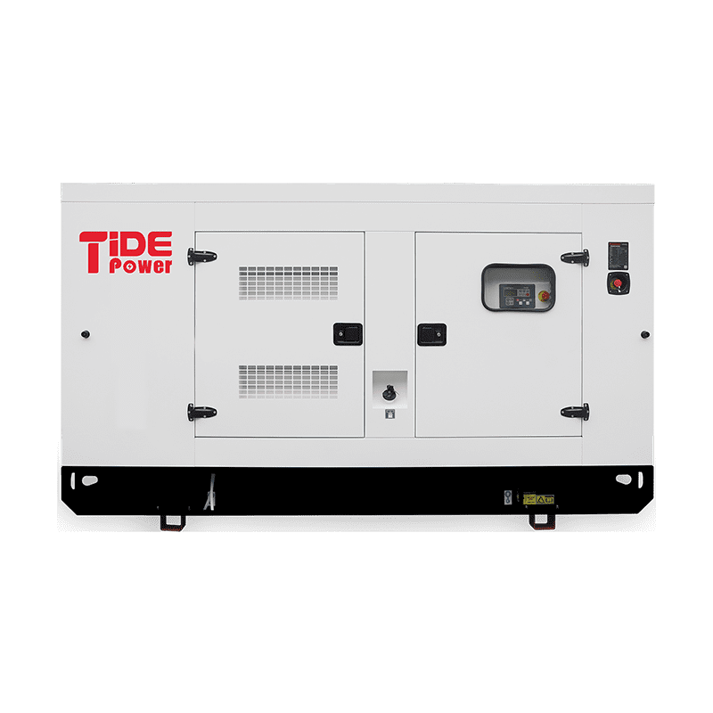
Recharge is the load that sizing calculations most often leave out. After an outage the battery has to be refilled, and the converters will accept charge power that adds directly to the site load. Size the generator for critical load plus the charge power the system will actually draw, inside the generator’s own preferred loading band, or the site will run longer than planned after every event and enter the next outage at a lower state of charge.
Redundancy is one way to buy firm capacity, and it is not free. Two smaller units in parallel can carry the load with one out of service and allow maintenance without an outage. The price is control complexity: synchronization, load sharing, reverse power protection, and a controller that behaves correctly when one unit drops offline under load. A single larger unit has fewer ways to fail, but it has no maintenance window and no partial-capacity fallback.
Paralleling several smaller generating units raises availability only where load sharing and synchronization are engineered rather than assumed. <Successful Synchronization of 7 Gas Gensets in Africa> covers a multi-unit synchronization project built around seven gas generator sets.
Fuel belongs in the same discussion. Diesel stored for long periods needs testing and polishing before it is trusted in an emergency, and a gas supply has to be characterized by pressure and composition, because methane number and heating value change what a gas engine can deliver. A generator selected against pipeline-quality gas can underperform on a site fed by variable biogas, and no amount of maintenance recovers output the fuel cannot support.
Battery storage sizing for power, energy and aging
Storage has two independent ratings and confusing them causes most disappointment. The converter sets the largest load step the battery can serve. The stored energy sets how long it can serve it. A battery with generous kilowatt hours behind an undersized converter still cannot start the pump.
The arithmetic is simple enough to check on paper. A 100 kWh pack behind a 50 kW converter is a two-hour system at full output; the same pack behind a 100 kW converter is a one-hour system. Neither statement says anything about what the site needs, because the duty cycle decides that.
| Duty | What sets the power rating | What sets the energy rating | Check to request |
|---|---|---|---|
| Ride through an outage until the generator takes load | Largest motor start plus critical load | Length of the start and transfer sequence | Measured sequence time under real load |
| Shift solar output into the evening peak | Converter rating against site peak | Evening demand minus direct daytime use | Daily load and solar profile for the worst week |
| Peak shaving against a demand cap | Site peak minus the target cap | Duration of the peak events | Twelve months of interval meter data |
| Reduce generator run hours | Battery and converter rating | Overnight load energy | Modelled fuel saving against measured load |
| Black start of a larger system | Converter overload and grid-forming capability | Energy for auxiliaries and transformer inrush | Black start procedure with a test record |
Storage sizing arguments usually focus on kilowatt hours, while the converter rating is what decides which loads the site can pick up. <Unlocking Energy Independence & Savings: Tide Power’s Scalable BESS Solutions for C&I Applications> covers scalable battery storage options for commercial and industrial applications.
Nameplate capacity, usable capacity and end-of-warranty capacity are three different figures. A warranty is normally written against a retained capacity threshold at a stated cycle count, temperature and charge rate, so the number that matters for reliability is the capacity at the end of the warranty period, not the capacity on the first day. Ask for the test conditions behind that figure before comparing two products on price.
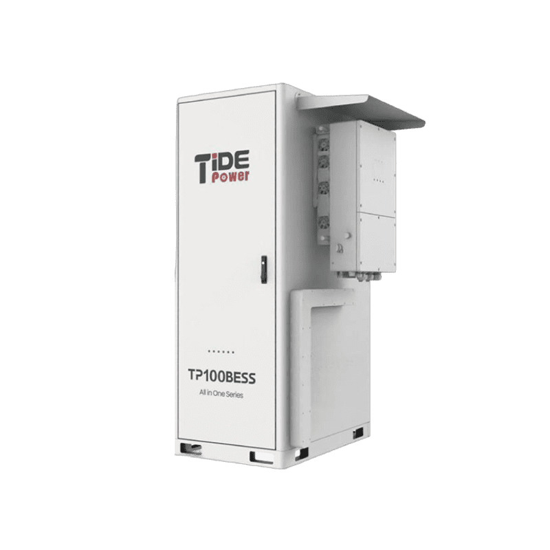
Cell temperature moves capacity, charge acceptance and aging, which makes thermal management part of the energy balance rather than an accessory. A container in a hot climate spends part of its stored energy keeping the cells comfortable, and a design that ignores cooling load loses usable energy it had counted on. Round trip efficiency works the same way: every stored kilowatt hour returns slightly less, and the difference is paid for in generator run hours and fuel. An efficiency claim is only meaningful alongside the charge and discharge power at which it was measured.
UL 9540A evaluates thermal runaway fire propagation in battery energy storage systems at cell, module and unit level [4]. What it supports is a comparison of how a given design behaves under a defined propagation test. What it does not do is approve a specific site layout, separation distance or suppression design; those come from the applicable installation standard and the authority having jurisdiction. Reading a propagation test report as site approval is a common and expensive mistake.
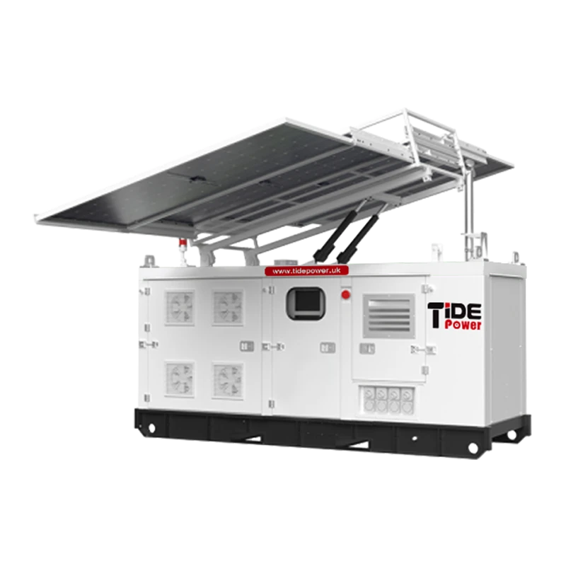
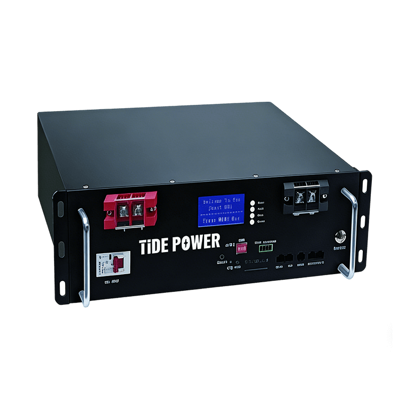
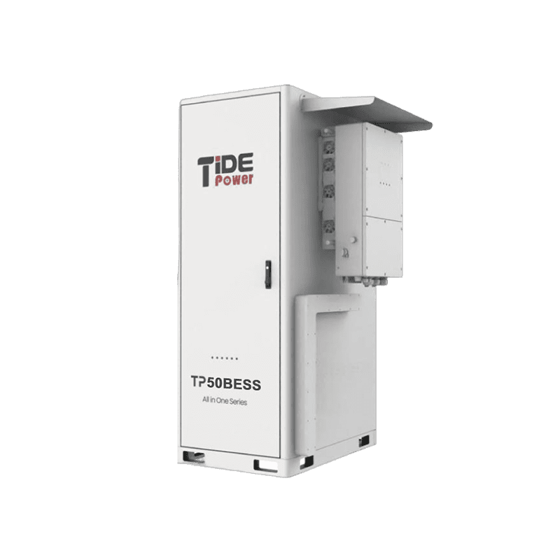
Modular storage changes the arithmetic without changing the principle. Tide Power’s hybrid power system, for example, builds energy in LFP blocks of 5.12 kWh and 16.1 kWh and offers battery units from the TP-50BESS to the TP-261BESS alongside hybrid power units rated from 10 kVA to 250 kVA. Modularity makes energy easy to scale in steps. It does not raise the converter ceiling, so the power rating still has to be matched to the load step separately.
Controller behavior across grid, island and black start modes
The controller is where all six factors meet. It decides which source carries the load, when a generator starts, how load is shared, how the battery recharges and when non-critical load is shed. Most of those decisions stay invisible until a transition fails.
Four states need a written behavior: grid connected, islanded, in transition and black start. Each one has a different source of voltage and frequency reference, so each needs its own answer to the same questions. What starts, in what order, after what delay, and what happens if the first attempt does not hold.
Transition design is a choice between two mechanisms with different costs. An open transition drops the load for an interval and depends on the loads riding through it. A closed transition overlaps the two sources, which requires synchronization and protection that survives the overlap. Vendor figures describing millisecond-level switching are useful only next to the ride-through tolerance of the loads on that bus, and the transfer has to be verified under real load rather than shown in a table.
A black start is not a larger version of an island transition. On a dead bus there is no voltage reference, so at least one source must form voltage and frequency while energizing transformer and motor inrush. Grid-forming capability, a staged load pickup sequence and a defined retry logic decide whether the first attempt succeeds. If the only grid-forming source is a battery with limited overload capability, the pickup sequence has to respect that limit instead of assuming the generator will cover it.
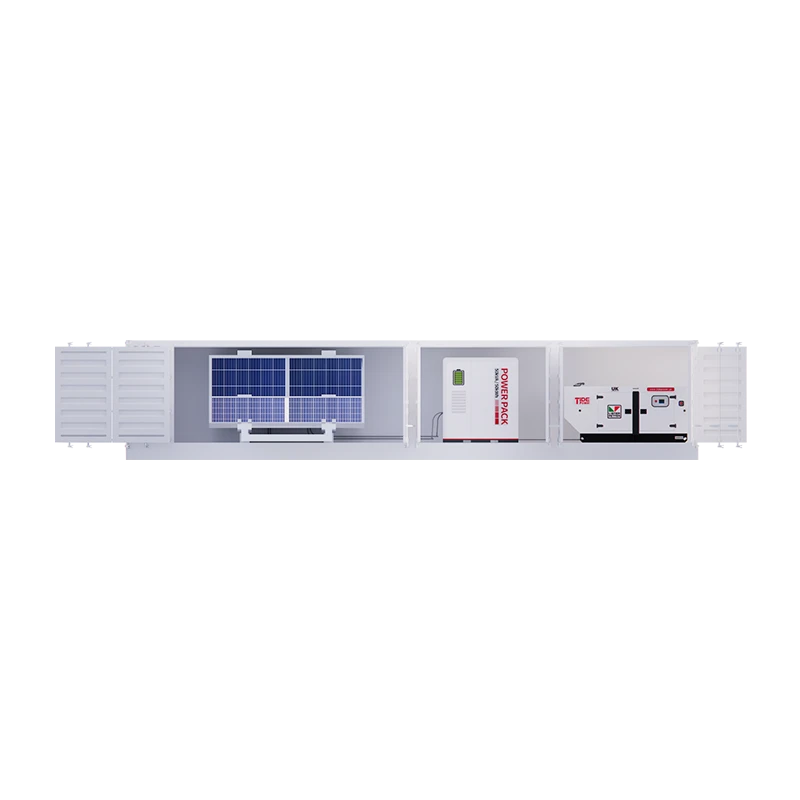
Communications add failure modes that have nothing to do with energy. A controller that needs a network link and a cloud service to make a dispatch decision has two more ways to stop working. Ask what the local controller does when a sensor or link fails: hold the last value, fall back to a defined safe state, or alarm and continue on a simpler rule. Any of those answers can be acceptable; an undefined answer is not.
A hybrid architecture pays back only where dispatch logic is specified as tightly as the hardware. <Tide Power Unveils Advanced Hybrid Power Solutions, Redefining Industrial Energy Resilience> covers hybrid power configurations aimed at industrial energy resilience.
Protection coordination when the fault current changes
Fault current in grid connected mode comes mostly from the utility transformer and is large. In island mode it comes only from the inverters and generators on site, and inverter current is limited by its own control. The current a feeder relay sees can therefore be a small fraction of the grid connected value. Settings that are correct in one mode can be wrong in the other, and the dangerous direction is the one where a fault does not clear.
The sequence that follows is predictable. A fault holds on, bus voltage stays depressed, inverters trip once their ride-through window expires, generators trip on their own protection, and the site goes dark. The event is reported as a system collapse. The cause is a coordination gap that existed from the day the relays were set.
Specify the study before the equipment. Ask for fault current calculations in every mode at the weakest source configuration, relay setting groups selected by mode, and, where one setting group cannot cover both modes, a communication-assisted or differential scheme. Fuse selection needs the same treatment, particularly where a fuse coordinated with the utility is expected to protect a feeder that is now fed by an inverter.
Grounding needs separate attention because an islanded source may not present the same ground fault path as the utility. On a high-resistance grounded or ungrounded island, a single line to ground fault produces little current, so overcurrent protection will not see it. Insulation monitoring or sensitive earth fault protection is the usual answer, and the decision belongs in design, not in commissioning.
IEEE 1547-2018 sets interconnection and interoperability requirements for distributed energy resources and their interfaces with the electric power system [5]. It defines interface behavior a utility will expect, including how a resource rides through disturbances and when it must stop energizing. It does not replace the site protection study, because fault levels, settings and coordination remain specific to the microgrid being built.
Load behavior and power quality at the point of connection
A load list is a summary, but the load is a profile with events, and the events decide whether the island survives. A motor start, a welder striking an arc, a chiller staging on, a bank of chargers switching in together. Each one is a transient the source has to absorb.
A direct on line motor start draws several times its running current for a few seconds. In island mode the source impedance is higher, so the same start produces a deeper voltage dip than it would on the utility. A drive on the same bus may trip on undervoltage, which stops production rather than just the motor. Soft starters, reduced-voltage starting and drives reduce the dip, but they add harmonic current and their own failure modes, so the trade is not one-directional.
Distorted current behaves differently on a weak source. Rectifiers, drives, LED drivers and chargers inject harmonic current, and the same current produces more voltage distortion when the source impedance is higher. Capacitor banks can create a resonance that amplifies one harmonic order well beyond what the individual loads suggest. A harmonic survey at the point of common coupling shows what the islanded source will actually see, which is not the same as the sum of the equipment nameplates.
Frequency behavior needs its own check. A small microgrid carries little rotating inertia, so a load step produces a larger frequency excursion than the same step on a large grid. Recovery depends on governor response, inverter droop settings and whether load shedding is armed and tested. The frequency nadir, not the steady-state value, is the number that decides whether the site rides through.
Single phase loads deserve a line of their own, because a three-phase island source with a heavy single-phase load can overload one leg while total load sits comfortably inside the rating. Imbalance also shows up as voltage imbalance that trips drives and upsets control electronics.
The executable checks are simple to list and often skipped: at least a week of interval data including start events, a motor list with starting methods above the threshold that matters for the site, a harmonic survey at the point of common coupling, and a load step test performed on the islanded source with the largest step the site will actually apply.
Commissioning tests and operating discipline that keep reliability
Untested reliability is a claim. Commissioning is where design assumptions meet the equipment that was actually delivered, and its useful output is a set of records with pass criteria agreed before each test runs, not a signed sheet at the end of the week.
Tests that should precede acceptance
- Black start from a dead bus, with the load pickup sequence timed and recorded.
- Grid to island transition at light, medium and peak load, not at a convenient single point.
- Island to grid resynchronization, including one deliberate failed synchronization attempt.
- Load rejection and load acceptance on each source, at the step sizes the site will produce.
- Protection operation in island mode, tested at the settings used in that mode rather than at the grid connected settings.
- Loss of communication and loss of a sensor signal, to confirm the controller reaches its defined fallback state.
- Battery charge and discharge at rated power, with cell temperature recorded throughout.
- Repeated generator starts from cold, which measures starting reliability instead of a single successful start.
What keeps the design reliable after handover
Settings drift, firmware updates, aging cells, degraded fuel and clogged filters all move the system away from the state it was tested in, and none of them announces itself. A workable routine includes state of health trending against the warranty curve, fuel testing and polishing where diesel is stored, thermal management service, a protection retest whenever settings or firmware change, and an alarm list with a named owner and a response time. Unattended operation is a design output rather than a default: it depends on remote monitoring, defined autonomy, and someone accountable when an alarm arrives.
Spares belong in the same plan. A proprietary controller card with a long lead time is a reliability exposure that no amount of redundancy in the power path repairs, because the redundant sources still need a controller to dispatch them.
IEEE 2030.8-2018 addresses testing of microgrid controllers and gives a useful reference for what a controller test program should cover [6]. The pass criteria stay project specific: an acceptable frequency dip depends on the loads on that bus, not on a generic figure copied from another site.
What to send before you approve a microgrid design
A reliability review moves faster with six inputs, and they are the same six the factors above depend on, expressed in the form an engineering team can work from.
| Field | Why it matters |
|---|---|
| Interval load data for a week or more, including start events | Sizes converter power and exposes the inrush the island must survive |
| Critical load list with the ride-through duration required | Separates ride-through energy from daily shifting energy |
| Worst-case weather window for the site | Sets the firm capacity that battery and generator must cover between them |
| Generator rating category and fuel supply data | The rating basis and fuel quality decide the output actually available |
| Single line diagram with protection settings for both modes | Shows whether a fault clears once the utility stops feeding it |
| Whether the site will be attended or unattended | Defines alarm ownership, remote support scope and fallback behavior |
Send the load data, the critical load list and the single line diagram together, because the value comes from reading them against each other rather than in sequence. Our engineering team at Tide Power Technology Co., Ltd. can review the transition and protection assumptions against that site data before the equipment selection is fixed. Email [email protected] or call +86 591 2806 8999. A design review is not a substitute for site testing, and the transition and protection evidence still has to be demonstrated on the installed system.
FAQ
How is smart microgrid reliability measured?
Track availability of the defined critical load inside agreed voltage and frequency limits over a stated period, counting every operating mode and every transition. A single percentage hides which factor failed, so record the failure signature per event as well: transition failures, unplanned generator starts, load shed events, and battery state of health against the warranty curve. A site with 99 percent availability and four transition failures per year has a different problem from a site with the same availability and none.
How much battery capacity does a microgrid need?
Split the question. Power must cover the largest load step plus the critical load. Energy must cover the ride-through duration, divided by usable energy, then adjusted for degradation at end of warranty. Finally, check whether the generator can recharge the battery within the interval between outages. Without a measured load profile and a stated ride-through duration, any capacity figure is a guess dressed as a specification.
Do I still need a generator if I have solar and storage?
It depends on the longest window the site must survive, not the average day. If the site has to ride through several consecutive low-sun days, storage alone becomes expensive and a generator is usually the cheaper firm capacity. If outages are short and the critical load is small, storage plus grid may be sufficient. Decide the survival window first, then choose the source mix that covers it at the lowest total cost.
Can a smart microgrid run unattended?
Yes, when unattended operation is designed in rather than assumed. That means remote monitoring, defined fallback behavior on sensor or communication loss, automatic load shedding with tested settings, and someone accountable for alarms with an agreed response time. A controller that sends alarms into an unmonitored inbox is not unattended operation, it is an unmonitored site with a data connection.
What causes most microgrid failures during a grid outage?
The transition and the protection, in that order. Loads that cannot ride through an open transition, a generator that does not start or accept load quickly enough, and relay settings that no longer see a fault once the utility stops contributing current. Equipment quality matters, but these three account for the failures that a commissioning program is designed to catch before the site depends on them.
References
[1] IEC 62898-1:2017, “Microgrids, Part 1: Guidelines for microgrid projects planning and specification,” IEC, 2017.
[2] IEEE 2030.7-2017, “IEEE Standard for the Specification of Microgrid Controllers,” IEEE, 2017.
[3] ISO 8528-1:2018, “Reciprocating internal combustion engine driven alternating current generating sets, Part 1: Application, ratings and performance,” ISO, 2018.
[4] UL 9540A, “Test Method for Evaluating Thermal Runaway Fire Propagation in Battery Energy Storage Systems,” 4th ed., UL, 2019.
[5] IEEE 1547-2018, “IEEE Standard for Interconnection and Interoperability of Distributed Energy Resources with Associated Electric Power Systems Interfaces,” IEEE, 2018.
[6] IEEE 2030.8-2018, “IEEE Standard for the Testing of Microgrid Controllers,” IEEE, 2018.
If you’re interested, check out these related articles:
Tide Power wishes you a Happy Lantern Festival
Tide Power Shines at Middle East Energy 2025 with Premium Energy Solutions
Tide Power Set to Make Waves at 2024 Middle East Energy Exhibition (MEE)
?Tide Power shines with new products at the Jakarta International Expo