 EN
 ZH
 FR
 ES
 AR
A submersible dewatering pump is a sealed electric pump that sits in the water it is moving and pushes flow through a discharge hose or pipe. It is used for construction sumps, mine dewatering, flood response, basement drainage, and temporary site water control. The basic decision is not just pump size. The pump must match the water condition, flow and head, electrical supply, and duty cycle. A pump that is oversized for the head or undersized for solids can fail early or leave water behind. This guide explains the working parts, sizing inputs, power choices, and checks that keep a submersible pump running.
What a Submersible Dewatering Pump Is and Where It Fits
A submersible dewatering pump is not the same as a surface pump that pulls water up through a suction hose. The submersible motor is inside the water, so the pump does not need priming and does not lose suction lift in the same way. The water cools the motor, and the impeller lifts water through the discharge connection.
That design fits sumps, pits, cofferdams, mine shafts, and temporary drainage points where the water level changes. It also fits emergency response when a crew needs to move water quickly from a low point.
The water condition decides the pump family. Clear water pumps move more volume for a given size. Solids handling pumps tolerate sand, silt, or small debris, but they often give up some efficiency. Trash pumps and vortex impellers handle larger solids but may need more power for the same flow. The right choice depends on what is in the water, not only on the discharge size.
How the Pump Moves Water
Inside the pump, the motor turns a shaft that drives an impeller inside a volute casing. The impeller adds energy to the water, and the volute converts that energy into pressure at the discharge. The pump curve shows the relationship between flow and head. As head rises, flow usually falls.
The water boundary matters as much as the impeller. A mechanical seal, cable entry, and motor housing keep water away from the windings. A worn seal or a damaged cable can let water into the motor, and the failure may appear as an overload trip rather than a visible leak.
Impeller design sets the solids limit. An open or semi-open impeller can pass some debris but may wear faster in abrasive water. A vortex impeller creates a passage for solids and reduces clogging, but it may need a larger pump for the same flow. A grinder or cutter pump handles fibrous material, but it adds maintenance points and should not be used where the wrong material can damage the cutting system.
Sizing Flow and Head Before You Buy
Start with the required flow at the discharge point, then calculate total dynamic head. Total dynamic head is the static lift from the water surface to the discharge point, plus friction loss in the hose or pipe, plus any discharge pressure at the outlet. The pump must produce the required flow at that head, not at a lower head on the test bench.
The pump curve is the decision tool. A pump can be selected for one duty point, but the actual operating point depends on the system. A long, narrow hose adds friction. A high discharge point adds static head. A partly closed valve adds resistance. If the actual head is higher than the selected point, flow drops and the pump may run outside its efficient range.
| Sizing input | What to record | Why it matters |
|---|---|---|
| Flow | Required discharge volume per minute at the duty point | Sets pump size and discharge pipe diameter |
| Total dynamic head | Static lift plus friction loss plus discharge pressure | Moves the operating point along the pump curve |
| Water condition | Clean water, sand, silt, or trash content | Determines impeller type and solids handling |
| Power supply | Voltage, phase, frequency, and available amps | Prevents motor overload and wrong starter selection |
| Duty cycle | Intermittent, continuous, or standby | Affects motor cooling and maintenance interval |
| Site layout | Sump depth, hose run, elevation, and access | Explains installation limits and service access |
A pump with excess head capacity can be throttled, but a pump with too little head capacity cannot be fixed by opening the valve. The better choice is to select a pump that meets the duty point with some margin for fouling and wear, then confirm the motor load at start-up.
Power Supply and Electrical Protection
Electrical supply is part of pump selection. Check the motor nameplate voltage, phase, frequency, full load current, and starting current against the available supply. Then check the cable size, cable length, overload protection, ground fault protection, and control method. A pump that starts and runs on a bench may still trip on site if the cable run is long or the supply is weak.
Long cable runs cause voltage drop. The motor draws higher current when the voltage is low, and the overload relay may trip before the pump reaches full flow. A cable that is too small for the run adds the same problem. The cable should be supported so its weight does not pull on the seal or terminal housing.
Generator backup adds another check. The generator must be sized for the pump motor’s starting current, not only its running load. A soft starter or variable frequency drive can reduce starting current, but it adds controls that need protection and training. Float switches and dry-run protection are also part of the electrical design, because a pump that runs without water can overheat quickly.
Remote Site Power and Backup
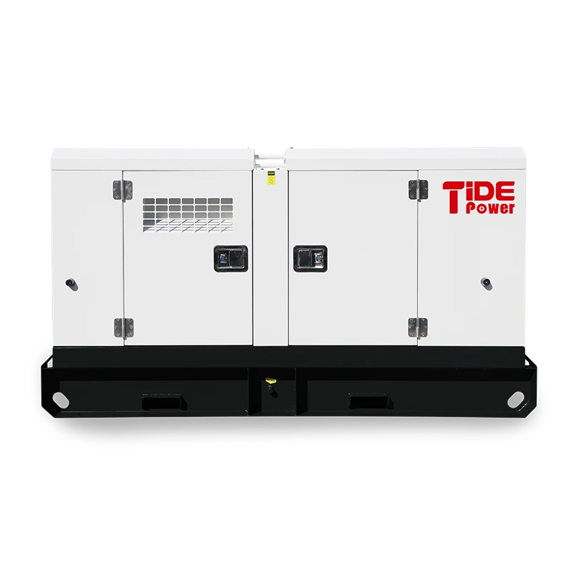
Remote sites change the power decision. Grid power may be unavailable, unreliable, or expensive to extend. A generator can carry the pump load, but fuel delivery, exhaust location, noise limits, and service access all become part of the installation. The generator should be sized for the pump’s starting current and for any other load that runs at the same time.
Fuel logistics often decide the practical choice. A site that runs a pump for a few hours a day can use a smaller generator than a site that runs continuously. A remote sump with no reliable fuel supply may need a hybrid system or a battery buffer to reduce generator run time.
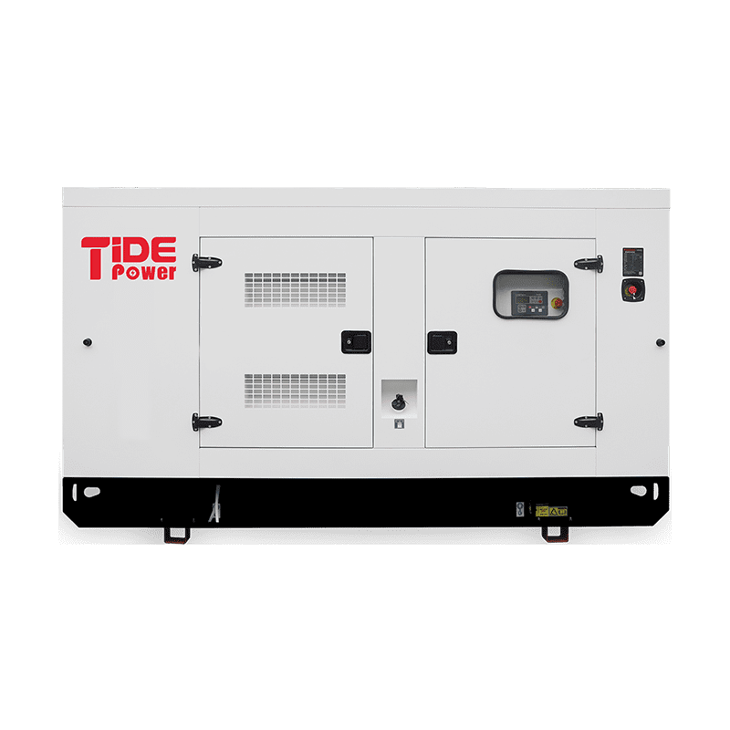
Noise-sensitive sites need more than a standard open set. Hospitals, residential areas, and night operations may require an acoustic enclosure and a exhaust strategy that keeps noise within site limits. The enclosure must still provide cooling air and service access, so the installation layout matters as much as the generator rating.
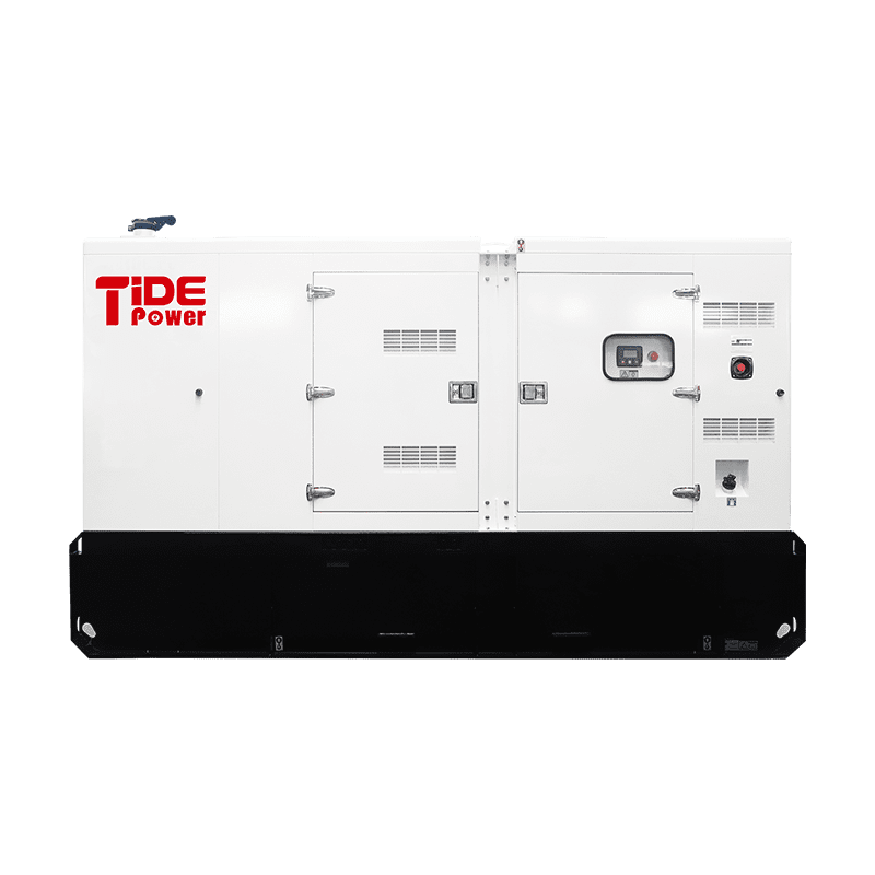
Heavy continuous loads need a generator with an adequate duty rating and a maintenance plan. Starting current, load steps, and ambient temperature all affect the generator’s ability to carry the pump without overload. A unit selected only for running load may trip when the pump starts against a full discharge line.
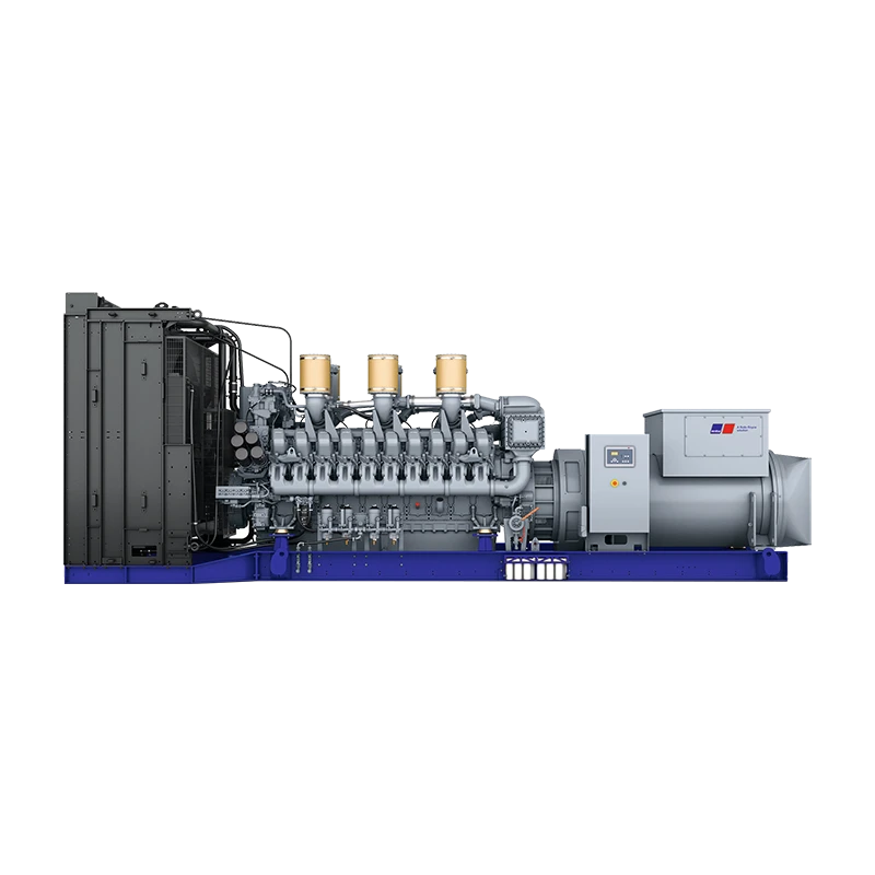
Hybrid and battery storage options can buffer starting current and reduce generator cycling. They can also support the pump during short outages, but the battery capacity, inverter rating, and control logic must match the pump load. A storage system that is too small will simply shift the overload to another component.
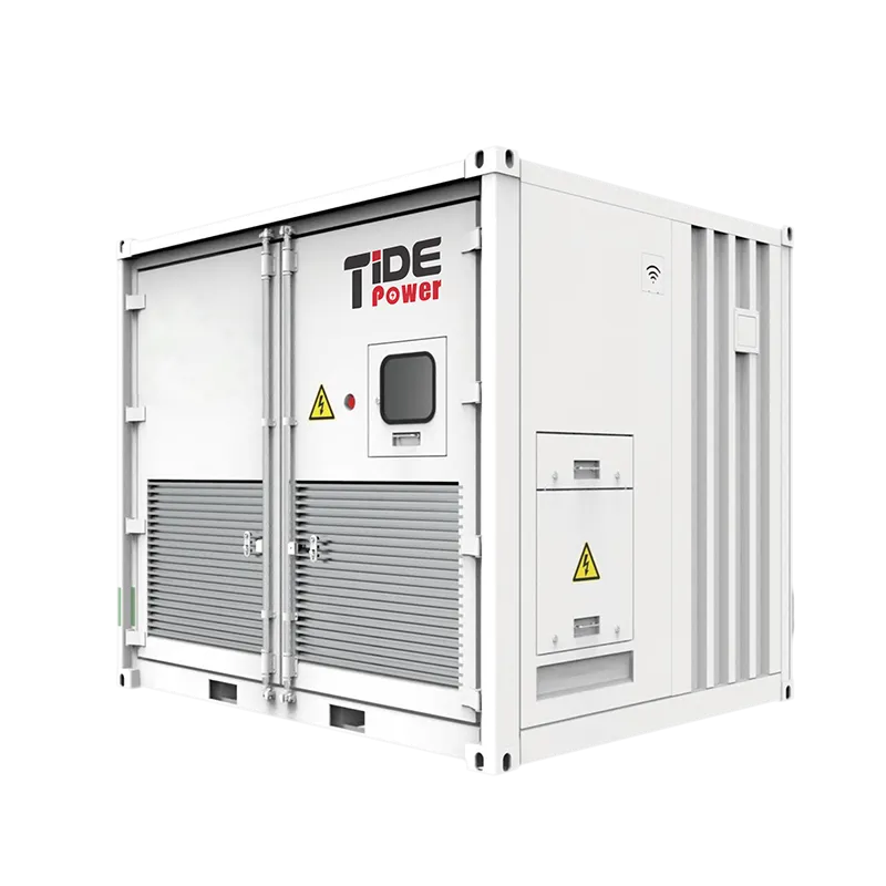
Where grid power is unavailable, some sites use diesel-driven pump sets instead of electric submersibles. That choice can simplify fuel logistics but adds exhaust, noise, and maintenance checks. > Diesel-driven pump sets remain a practical alternative where grid power is unreliable or unavailable. <Diesel Pump Generators: Reliable Dewatering Solutions for Harsh Environments> covers how diesel pump generators handle dewatering in harsh environments.
Installation and First-Start Checks
The sump must be deep enough for the pump to sit below the water level during operation. The intake needs clearance from the bottom so it does not pull in sand and debris. A pump set directly on soft silt can bury its intake and lose flow. A stand or gravel pad can keep the intake clear.
The discharge hose should be as short and straight as the site allows. Sharp bends, kinks, and undersized fittings add head and reduce flow. The hose must be supported so it does not pull on the pump outlet. The cable should be secured away from the discharge and not used as a lifting rope.
Before start-up, confirm the pump is fully submerged, the float switch moves freely, and the discharge valve is in the correct position. Check the direction of rotation where the motor is phase-sensitive. Start the pump and record the amp draw, discharge pressure, and flow. If the amp draw is high or the flow is low, stop the pump and check the supply, the impeller, and the discharge line before running it again.
Do not run the pump dry. A dry run can overheat the motor and damage the seal in a short time. If the sump empties faster than the pump can recover, use a cycle control or a larger sump so the motor has enough water to cool.
Maintenance and Failure Prevention
Maintenance starts with the water condition. Abrasive water wears impellers, seals, and wear plates. Clean water allows longer intervals, but the pump still needs inspection after flood work or heavy site use. Keep a log of amp draw, flow, and discharge pressure so a change is visible before a failure.
| Symptom | Likely cause | First check |
|---|---|---|
| No flow after start | Air lock, wrong rotation, or blocked intake | Confirm priming, rotation, and intake clearance |
| Low flow | Worn impeller, high head, or clogged discharge | Compare pump curve, inspect impeller, check hose |
| Overload trip | Voltage drop, wrong cable, or binding impeller | Measure supply voltage and amp draw |
| Seal failure | Abrasive water, dry running, or damaged cable | Inspect oil chamber and cable entry |
| Vibration | Debris, bent shaft, or loose mounting | Isolate power and inspect rotating parts |
Seal condition is a common limit. A seal that has been run dry or exposed to abrasive silt can leak into the motor chamber. The first sign may be a ground fault trip, not a visible leak. Cable entry is another weak point. A cable that is pulled, pinched, or repeatedly bent at the pump handle can open a path for water.
Cost drivers follow the same pattern. Abrasive service increases impeller and seal replacement. Clogging increases labor and downtime. Overheating shortens motor life. A maintenance plan that includes intake cleaning, amp checks, and seal inspection is usually cheaper than replacing a burned-out motor.
Next Step for Your Dewatering Pump Selection
Send the required flow, total dynamic head, water condition, voltage, phase, cable run, duty cycle, and site access details. Tide Power Technology Co., Ltd. can review the pump and power package against those inputs and identify the checks needed before installation. Email [email protected] or call +86 591 2806 8999.
FAQ
What is the difference between a submersible dewatering pump and a sump pump?
A sump pump is usually a small pump for basement or building drainage. A submersible dewatering pump is built for temporary or heavy-duty water control on construction sites, mines, and flood response. The dewatering pump often has a larger motor, a higher head range, and a more rugged cable and seal system. The right choice depends on flow, head, solids, and how long the pump will run.
Can a submersible dewatering pump run dry?
It should not. The water cools the motor and lubricates the seal area. A pump that runs dry can overheat, damage the seal, and trip the overload. Use a float switch, level control, or a sump that keeps the intake submerged. If the water level drops faster than the pump can recover, stop the pump and adjust the cycle.
How do I choose between generator and grid power for a remote pump?
Start with the available supply and the pump motor’s starting current. Grid power is usually simpler if the connection is close and reliable. A generator makes sense when the grid is unavailable or the pump is temporary. Size the generator for starting current, fuel logistics, noise limits, and service access. A hybrid or battery buffer can help if the load is intermittent.
What maintenance does a submersible dewatering pump need?
Check the intake, impeller, seal, cable entry, and amp draw. Clean debris from the strainer and discharge line. Confirm the float switch moves freely. Record flow and pressure after each service so a drop is visible. Abrasive water needs shorter inspection intervals. Replace worn seals and impellers before the motor is damaged.
Why does my pump lose flow when the discharge hose is long?
A long hose adds friction loss, which raises total dynamic head. The pump moves to a different point on its curve, so flow falls. Sharp bends, undersized fittings, and a high discharge point add the same effect. Check the hose size, length, and layout before changing the pump. A larger hose or a shorter run may recover flow without a new pump.
If you’re interested, check out these related articles:
How to Choose a Generator at Tide Power
Tide Power 2025 Global Sales Annual Meeting & Team Activities Conclude Successfully
Powering Africa: The Role of Tide Power in the Local Industrialization Process
Light Up the Night, Sustainably: The Solar Hydraulic Lighting Tower Revolution
A delegation from the CCPIT Fujian visit to Tide Power